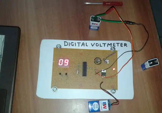
Note : Pin connection should be in according to code below. if any confusion then ask in comments below...
//PB 0=BUZZER

//PB1=LDR SENSOR

//PC2=SMOKE SENSOR

//PC0=ANALOG INPUT(TEMPERATURE SENSOR)

//PC3,PC4,PC5=E,RW,RS( 16X2 LCD)

//PD=DATA(16X2 LCD)

#define F_CPU 12000000UL //Setting F_CPU to the frequency of the microcontroller

#include <avr/io.h>

#include <avr/interrupt.h>

#include <util/delay.h>

#include <stdio.h>

#include <stdlib.h>

#include <string.h>


/*ADC Conversion Complete Interrupt Service Routine ()*/

ISR(ADC_vect);

////////////////////// ////////////////////////// ////////////////////////// ////

void InitADC()

{

    DDRC = 0b00111000;                    // Configure PortA as input

    ADMUX=(1<<REFS 0);                // For Aref=AVcc;

    ADCSRA=(1<<ADE N)|(7<<ADPS0);

}
int ReadADC(int ch)
{
ch=ch&0b00000111 ; //Select ADC Channel ch must be 0-7
ADMUX|=ch;
ADCSRA|=(1<<AD SC); //Start Single conversion
while(!(ADCSRA & (1<<ADIF))); &n bsp; //Wait for conversion to complete
ADCSRA|=(1<<AD IF); //Clear ADIF by writing one to it
return(ADC);
}
////////////////////// ////////////////////////// //////////////////////////
#define SELECT_7SEG_DDR DDRC
#define SELECT_7SEG_PORT PORTC
#define DISP1 PC5
#define DISP2 PC4
#define DATA_DDR DDRD
#define DATA_PORT PORTDchar DECODE_7SEG[11] = {0x77,0x14,0xb3,0xb6,0xd4, 0xe6,0xe7,0x34,0xf7,0xf6,0 x08};
void DISPLAY_7SEG(int a)
{
SELECT_7SEG_DDR |= (1 << DISP1) | (1 << DISP2);
DATA_DDR = 0xff; // port assigned as output
char char1;char1 = a%10;
a = a/10;
char1 = DECODE_7SEG[char1];
SELECT_7SEG_PORT &= ~((1 << DISP1) | (1 << DISP2));
DATA_PORT = char1;
SELECT_7SEG_PORT |= (1 << DISP1);char1 = a%10;
a = a/10;
char1 = DECODE_7SEG[char1];
SELECT_7SEG_PORT &= ~((1 << DISP1) | (1 << DISP2));
DATA_PORT = char1;
SELECT_7SEG_PORT |= (1 << DISP2);
}int main()
{
DDRC &=~(1<<PC0);&nbs p; //PC2=LOW INPUT FOR TEMPERATURE
DDRB|=0xFF; ; //Output for relays
PORTB = 0x00; //INITIAL VALUE
InitADC();unsigned int count;while(1 )
{
int temp_int=ReadADC(0);
DISPLAY_7SEG(temp_in t/10); & nbsp; for(count = 0; count<1000; count++)
{
DISPLAY_7SEG(temp_in t/10);
} }
return 0;
}For any query, feel free to comment below.....

Posted By :
Mahesh Nigam
(Scientist)
2019-09-27 17:13
See Author's other Published Topics
Peoples
Peoples
Comments...
Prashant Sharma: Mahesh nigam ji Your artical is good . I want to make a digital volt.eter and amp Meter using seven segment . Can u help me to provide a program I m using 3 segment display which have 12 pins in center. Model = SUNR056CA3D032020 COMMON ANODE . MY WHATSAPP NO. IS 9412582901
Mahesh Nigam(Scientist): Above article is only for volt meter and it is very old code. It was made by using three 7 segment display of 10pin. This will also compatible with 12pin three digit segment display with small change in pin connection. problem is that, this code is not for Current Meter. If you want to read both Voltage meter and current meter, we can provide it for you but it will cost you some amount. Contact me for more detail on +91-9125110098
Write Your Comment